EMERGENCY TOWER EVACUATION
September 17th, 2001
To contact the author: Jean-Pierre Petit, Astrophysicist, France
Translated by Benjamin Rottier
We’ve all seen how vulnerable skyscrapers are – just like the Twin Towers, Manhattan’s pride, built from steel and concrete.
Note, January 30th, 2008: I wrote these sentences on September 17th, 2001. When terrorists crashed their planes into the towers, they chose planes loaded with fuel, knowing that the resulting fire would cause the towers to collapse. Without this intense heat, the towers would have been severely damaged but still standing. This phenomenon of successive floor collapses is inevitable. If such an event were to happen again, building occupants must be able to evacuate within a very short time, before the heat can have its devastating effects.
It shows how readily we accepted the official explanations at the time. Things have changed since then.
After the fire in San Francisco, Americans, traumatized by its effects, began installing external staircases. But this solution isn’t feasible for extremely tall buildings. Here, we propose another solution worth considering.
Below is a general plan for evacuating people from towers, using cables. These cables are attached to drums located at various floors, depending on who needs to be evacuated. The central cable is meant for evacuating residents on one side of the building. To the upper left, there’s a mechanism for unwinding the cable. The drum is unlocked by activating a mechanism from inside, near the evacuation station. The cable is then pulled downward by a weighted device designed to prevent it from sticking to the building’s surface; its speed is controlled by an aerodynamic brake.
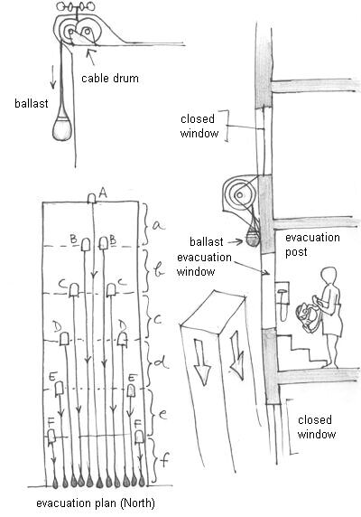
As noted by Canadian engineer Alexandre Berube, more cables would be needed for upper floors. With all due respect to my Canadian friend Norman, standard rappelling equipment and climbing ropes can’t be used here. The rope must be arranged in a zigzag pattern to attach the rappelling device; this isn’t possible if multiple people are descending simultaneously.
The “sock” evacuation system is quite ingenious. Long nylon tubes are unfurled along the building’s exterior. People climb into them through an opening at the top. Since these tubes are permeable, no one risks suffocating. Descent speed is controlled by friction between clothing and the tube’s interior surface. Everyone descends at roughly the same speed, regardless of height or weight. Norman pointed out that taller individuals have more contact area with the tube. Descent speed is about 2 m/s. Since the tubes don’t reach the ground, evacuation happens automatically. Of course, only one person can enter each tube at a time; however, adding more tubes would solve this issue. These devices are inexpensive and can be mass-produced. The only downside: if people wear short-sleeved shirts or shorts, friction could cause burns. But suffering minor burns is preferable to being buried under tons of debris, right?
One question: Are buildings in earthquake-prone areas equipped with such evacuation systems? Remember: when an earthquake occurs, even if the building doesn’t collapse, its distortion locks all doors shut. They become impossible to open. Also, like during fires, stairwells are among the first structures to be damaged. There are often multiple tremors as well. How many lives could have been saved if people could evacuate immediately upon sensing danger?
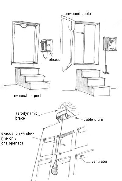
In the following diagram, we see an interior view of an evacuation station. Only certain windows can be fully opened, leading to a small platform where a few people can stand safely. Stairs allow quick access to this platform. You can see the cable being unwound (diameter: ~5 mm). Below, the cable unwinding mechanism and the aerodynamic brake.
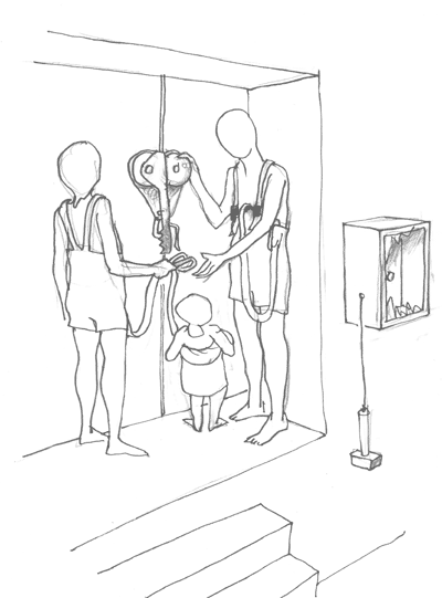
In the next diagram, a family (a couple with a child) prepares to descend. Their equipment will be described later.
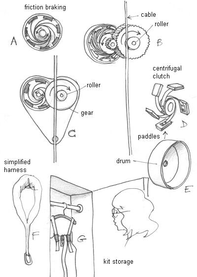
Below is the basic mechanism: a descent retarder that operates via friction. In A, we see a flexible paddle system derived from car clutches. In D, the paddles are shown outside their housing. These paddles interact with elements inside the drum (E). In B, the cable rubs against a roller connected to a gear that increases rotation speed. In C, a schematic diagram shows the roller and gear on the right, while on the left, braking paddles rotate within their housing. In G, there’s a storage compartment for two types of equipment; their coupling mechanisms differ. On the left, there’s a simplified harness similar to those used for helicopter rescues.
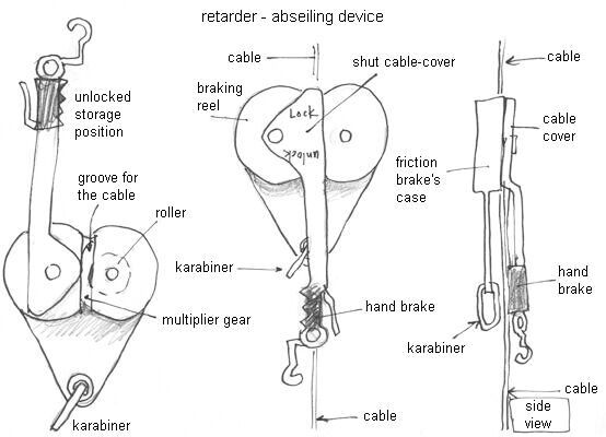
Next diagrams depict the complete descent retarder. The friction-based paddles are no longer visible; they’re housed within their casing. In A, the cable cover is in an unlocked position. The device is stored in a cabinet in this state, suspended by a hook. Below, there’s a plate connected to both casings; one contains a gear linked to a rubber roller. The plate includes a carabiner for attaching people. The cable is secured in a groove; it’s held tightly by a heavy weight. A tension spring prevents wind-induced movement. To secure the cable, turn the cover and braking handle 180°. In B, the system is ready for use. The triangular-shaped cover conceals the groove where the cable lies. This ensures the cable stays pressed against the roller. The braking handle is lowered. In C, a side view of the device.
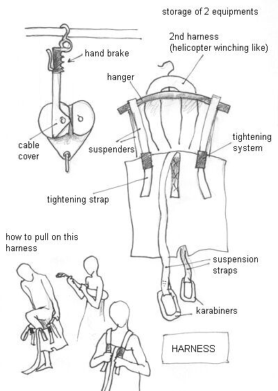
Next diagram shows storage setup. In A, the descent retarder hangs with the braking handle upward. The cable groove is visible. In B, there’s a nylon harness resembling pants; this helps evacuate unconscious or panicked individuals. Being rescued via helicopter or descending from 400 meters altitude surely feels very different. Elderly, disabled, or children shouldn’t be overlooked. In C, someone pulls on the harness. In D, he tightens the straps. Nearby, someone else wears a simplified harness. Suspension occurs via a nylon strap ending in a carabiner.
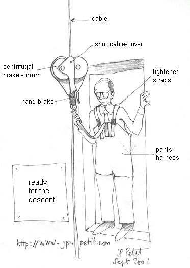
Below, a man prepares to jump. His descent retarder is set up. The cable cover is closed, ensuring proper contact between cable and rollers. He’s strapped to the device and holds the suspension strap in his right hand; his left hand grips the braking handle. None of these actions are strictly necessary, as the device can lower him automatically.
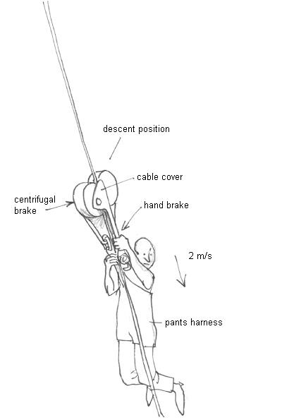
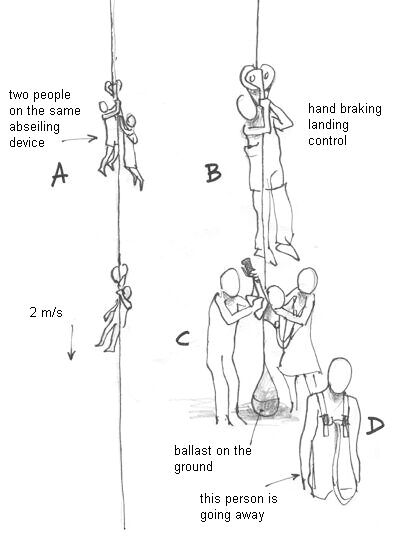
In this aerial view, someone descends. His left hand rests on the braking handle; theoretically, he’ll use it only near the ground to avoid colliding with others. A person of normal weight descends at ~2 m/s. Friction increases quadratically with speed; thus, if multiple people use the same device, or if they’re heavier, descent speed won’t rise significantly. When I used old-fashioned hemispherical parachutes, impact speed was around 6 m/s.
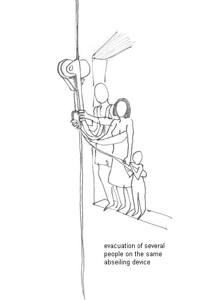
Next image shows several people using the same device. An operator at each platform attaches the descent retarder to the cable and connects it to individuals. He explains how to use the braking handle and checks everything before allowing descent.
Finally, people must be received safely. To expedite evacuation, they’re spaced apart along the cable. They must control their descent speed using the braking handle and maintain distance from those below. Two people play key roles: one waits on the ground to receive those descending (B); another quickly moves away (D).
Had such systems been installed on all four sides of the Twin Towers, thousands of lives could have been saved. But who could have predicted such horror?
Today, we know.
September 17th, 2001
Unwinding cables remains problematic, especially over distances exceeding several hundred meters, due to crosswinds. Cables mustn’t tangle; otherwise, people could collide. We initially considered using heavy weights. Yet no weight can tighten cables hundreds of meters long. Solution: secure cables at their base. Weighted shells (B) could be dropped (A) rapidly into shafts sealed with plastic covers strong enough to bear weight but brittle enough to shatter upon impact. Shells would align along conical guides; locking would be automatic.
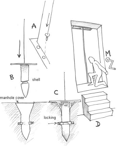
In D, someone can tighten the cable using a simple handle (M). If cables serve specific floors, unwinding and tightening can occur from multiple stations (some may be inaccessible).
We discussed a friction-based retarder inspired by car clutches. Alternatively, a James Watt-style flyball governor could maintain constant descent speed regardless of load (though its response is non-linear).
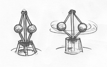
Flyball Governor
Under these conditions, manual brakes could be eliminated; this would be preferable. Otherwise, panicked individuals might grip brakes, halting evacuation. If everyone descends at similar speeds, spacing between jumps ensures enough time for ground personnel to assist newcomers.
All these ideas are merely thoughts I’ve jotted down. They suggest that existing buildings can be fitted with effective evacuation systems without major modifications. No one anticipated how terrorist attacks could compromise structural integrity. No firefighters, architects, or safety experts imagined that thousands of liters of fuel could weaken steel beams, causing floors to collapse like dominoes. In future, even the most far-fetched ideas deserve consideration.
One final note:
This text won’t be patented. Some things are more important than making money from security solutions. Human lives must be saved. Therefore, these ideas are freely available for anyone to use. When your house is on fire, you don’t bother tidying up the living room.
As of November 15th, 2001, number of connections: