The Mysteries of the B2
January 17, 2003 – Updated December 8, 2005
Page 7
A video shows the B2’s MHD system in action.
When one wants to keep something a secret, extreme caution is required. Sometimes, however, certain clues still get leaked. By entering:
http://www.is.northropgrumman.com/videos/b2_tx.wmv (archive from 07/01/2007)
into your browser, you can watch a 1-minute-and-16-second video, which can also be downloaded (1.9 megabytes). It contains numerous images of the B2 in flight; it depicts the bomber itself, not some hypothetical hypersonic version.
Here’s a brief key excerpt:
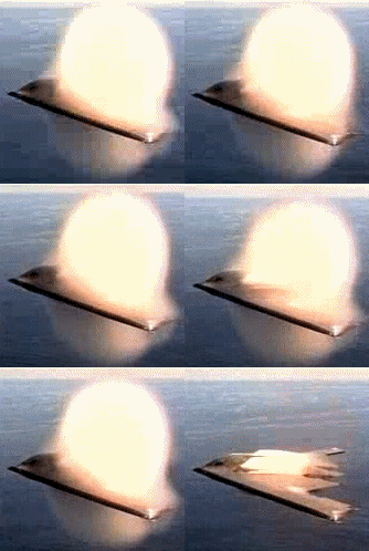
The B2 transitioning into transonic flight above the sea. Migration of the electric discharge (MHD) within a water vapor environment. Sequence isolated and converted into an animated GIF by Christophe Tardy. Note that the glow from the discharge affects only the upper portion of the aircraft.
The B2 is equipped with a plasma-generation system that utilizes ambient airflow as an MHD generator; this allows it to surround itself with plasma even when flying at subsonic speeds. This plasma isn’t visible during daytime. It renders the aircraft stealthy by absorbing and scattering radar waves. If this “demonstration B2” weren’t actually stealthy, people would naturally wonder why—since it’s reputed to be undetectable. In this video, this “minimal” MHD system is activated. Normally, the electric discharge shouldn’t be visible at all. But when the aircraft flies over the sea—an area saturated with moisture—it transitions into transonic flight. Below is a cross-section of a wing in transonic flight. As the aircraft approaches sonic speed, “compressibility” phenomena appear near the thickest part of the wing profile (marked by a dashed line).
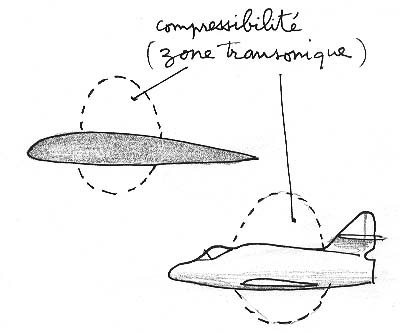
Wing and fuselage of an aircraft in transonic flight.
It’s precisely in this region that water vapor condenses; such condensation is usually fleeting, since aircraft aren’t designed for prolonged transonic flights—they become unstable at such speeds. When an aircraft crosses the sound barrier, it doesn’t linger at that speed range. The same applies when it slows down. Below is a photo of an F-18 flying transonically above the sea; it displays a cloud-like formation whose color is obviously white—because it’s simply water vapor.
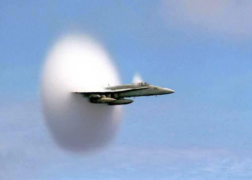
F-18 transitioning into transonic flight in humid air. (Photo provided by J. Costagliola.)
Other photos depicting the same phenomenon, provided by Gérard Chenu:
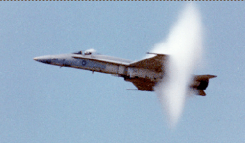
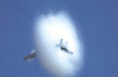
This link leads to a video showing an aircraft transitioning into transonic flight. It’s not some “crazy plane”; it’s a standard example in fluid mechanics:
http://www.incroyablement.com/images/videos/asf/avionfou.wmv
In the video featuring the B2, we observe something completely different. See the two images below:
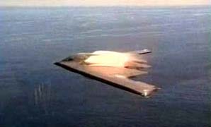
The electric discharge spreads throughout the transonic region where water vapor condenses.
Note the reflection of the glow on the wing’s upper surface.
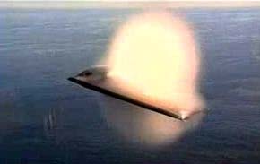
Second image extracted from the video: The vapor bubble reaches its maximum size. Same goes for the electric discharge.
What do we observe? On the upper portion of the aircraft—where the MHD system resides, mainly around the engine intakes and exhaust nozzles—the vapor bubble shines brightly. That’s logical: air filled with tiny water droplets conducts electricity better. Thus, the electric discharge tends to spread throughout this region. Evidently, this vapor bubble emits light caused by radiation from excited gas molecules colliding with free electrons forming the discharge. This luminosity is much weaker or nonexistent on the lower side of the aircraft.
How did the Air Force allow such images to leak? In our opinion, nobody paid any attention to them. Under normal circumstances (as seen in all other images from the video), the electric discharge remains invisible. It became visible only briefly because transonic flight suddenly increased the electrical conductivity of the surrounding air via water vapor condensation. These images were given to a company tasked with editing this one-minute-plus video. Nobody paid much heed to the abnormal coloration and brightness of the vapor bubble during this very brief sequence. Only a specialist could have noticed this anomaly.
Moral: Even when one tries hard to hide things, clues always remain.
In the image below, we see the same halo effect around the B2, but the MHD system isn’t activated.
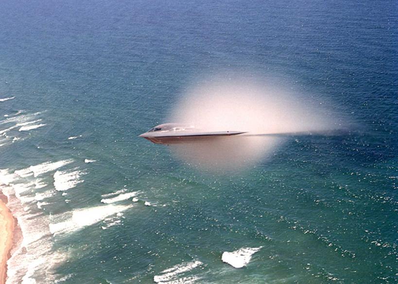
Halos of condensed water droplets surrounding a B2 in transonic flight; MHD system inactive. (Photo provided by J. Costagliola.)
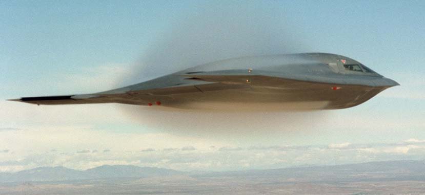
Another image, provided by Eric Dezoête. Clouds in the background indicate high humidity levels.
Sent by reader Laurent Molieras; found on an Air Force website:
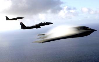
A strange image.
We again encounter this phenomenon of a vapor cloud forming near the wings of an aircraft in transonic flight. The reader raises two questions I can’t answer right away:
– Why doesn’t this happen on both escort fighters?
– Why does it affect only the upper wing surfaces?
A few notes: The aircraft fly through humid air (above the sea). We know that transonic compressibility effects are quite brief and occur only within a narrow speed range; they precede the formation of shock waves around an object. To be thorough, we should mention that air density can vary, not just pressure (“compressibility” and “decompressibility”). It’s also possible that all three aircraft aren’t flying at exactly the same speed; the B2 might catch up to the two fighters. However, this seems unlikely. Moreover, being bulkier than the fighters, the B2 might experience this phenomenon before them. Hence, condensation could occur on the B2 before appearing near the sleeker fighters. Finally, fluid dynamics experts might offer explanations as to why this occurs solely on the upper wing surfaces. Still, there’s something odd here. Let’s examine each aircraft’s attitude:
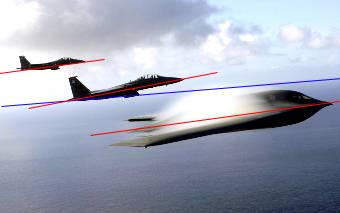
The B2 is supposed to operate at speeds near the lower limit of the transonic range. Under such conditions, it should fly at low angles of attack; see the image provided earlier by Dezoëte. Yet here, its angle of attack appears relatively high. If it’s flying horizontally, its speed would be significantly below transonic levels. But there’s no proof it’s flying horizontally; perhaps it’s ascending transonically after the pilot pulled back on the control stick. This reasoning applies to the second aircraft in the background, but not to the third, which hasn’t yet begun maneuvering.
According to someone who witnessed “glowing streaks” along the B2’s wings in 1997, Northrop Grumman and the USAF intend to make an announcement regarding this. Will they confirm that this glow results from activating their MHD system or an electric discharge? Or will they offer another explanation, like sunlight illuminating the vapor clouds? The second photo makes this explanation questionable. If it were sunlight, why wouldn’t the lower side of the aircraft be lit too? Under direct sunlight, such clouds would appear white, as shown above. We’ll have to wait and see...
This detail was noted by Philippe from Argenteuil.
January 26, 2003: Following a discussion with an expert, we learned something about radar stealth. There exist “frequency doublers” based on organic crystals; these are used in lasers. Thus, one can double the frequency of emitted laser light, originally produced in infrared wavelengths. For stealth purposes, the idea is to coat an aircraft with such material, causing it to reflect radar signals at twice the original frequency. Since antenna designers rarely account for this factor, the aircraft would technically be “detectable”; it would reflect a signal, but radar systems wouldn’t register it properly. This illustrates how even the most advanced technologies and creative concepts can be repurposed for military use. Such is life.
February 6, 2003
Today I received an email from Jacques Antoine, living in Namur, Belgium:
“I wish to contribute my own observations regarding B2 anomalies. In your latest book, the photo-montage on page 128 reminded me of an incident I dismissed as unimportant back in November 2002. Above my home (Belgium, Wépion, 6 km south of Namur), aircraft fly frequently. Over time, I’ve learned to identify aircraft types by ear. Curious about unusual engine noises, I grabbed binoculars (12x50) and noticed several heavy aircraft approaching, their engines unlike those of ordinary planes. Indeed, despite darkness, I saw a triangular formation of three aircraft heading roughly west-to-east along typical U.S. flight paths. Though it was dark, thanks to my binoculars, I discerned a conventional aircraft leading, flanked by two others whose lights seemed unusual; I identified them as B2s. What surprised me was faint whitish glow along their wing leading edges; I attributed it to moonlight, since the moon rose directly ahead of them (invisible to me due to dense vegetation). I was puzzled: how could both wings of one aircraft produce identical reflections? I chalked this up to poor observational conditions (using powerful binoculars at night to view distant moving objects for a short period). Regrettably, I failed to note the date, time, azimuth, apparent size, etc.; I merely assumed it was a routine military transport involving rare aircraft. Attached is a sketch of what I recall seeing three months later. Note that, per my memory, the bright area near the engine intakes appears narrower than in your published photo.”
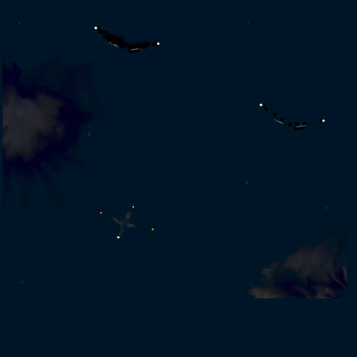
Observations by Jacques Antoine, Namur, late 2002.
February 11, 2003:
Actual low-infrared-signature B2 exhaust nozzles
Following a suggestion by de Panafieu, Christophe Tardy extracted brief clips from the Northrop-Grumman video and turned them into animated GIFs. First, we must note that whenever the B2 was presented publicly, photographing its rear was strictly prohibited. Why?
What would one see at the rear of such an aircraft? The way it expels burnt gases from its engines. Here’s an image (also taken from the video) matching the diagram included in the U.S. “B2-Spirit in Action” brochure:
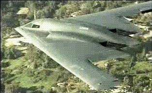
The “official” B2 exhaust nozzles.
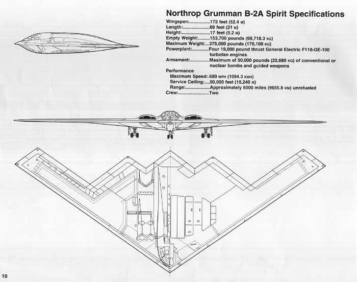
Three-view diagram showing placement of the “official” B2 exhaust nozzles.
Below is another image extracted from the brochure:
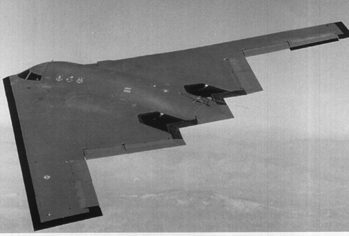
Another view of the “official” B2 exhaust nozzles.
True, the aircraft expels burnt gases from its upper wing surfaces, but this arrangement isn’t particularly stealthy. A year ago, we saw infrared photos of the aircraft’s rear in flight; they revealed two prominent glowing spots corresponding to exhaust vents. Yet the photographer himself, who took these daytime photos during a public demonstration, refused to let us publish them. This “compact” exhaust pattern suggests neither significant dilution nor any special effort toward infrared stealth. Infrared-sensing satellites exist.

Detection of the B2 via infrared satellite.
Under such conditions, the B2 would easily be detected; if it flew subsonically over vast distances, guided missiles could readily bring it down—thanks to constant tracking by said satellite. It’d be akin to shooting at a target moving at such speeds.
Here’s a plan view of the F-117A, far older than the B2, sporting a “duckbill”-shaped exhaust nozzle; I was the first to showcase it during a TV show hosted by Poivre d’Arvor, presenting a model reconstructed shortly before the Air Force released full photographic documentation.
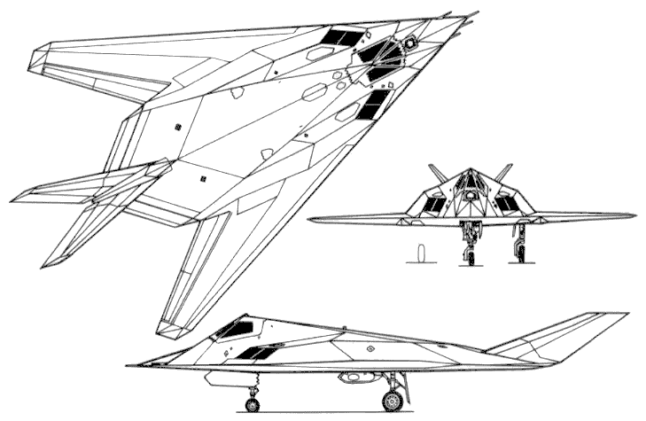
The stealth fighter F-117A.
This nozzle expels gases in a flat jet pattern, ensuring rapid dilution to minimize infrared signature. Now, let’s consider: what’s the best method to further reduce infrared emissions?
– Maximize dilution.
– Replace traditional nozzles with a slit along the trailing edge, perhaps just a few centimeters thick.
Technically feasible. Given the stakes, it’s worth developing a system where tubes channel exhaust along the entire trailing edge, or at least large portions thereof. Moreover, extensive dilution (“dual-flow” system) boosts propulsion efficiency. Should such technology be implemented, we’d observe a mirage effect at certain angles, affecting parts of the aircraft not meant to emit hot gases. Observe these excerpts isolated by Christophe Tardy:
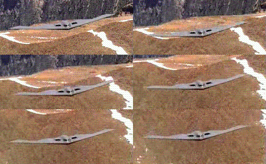
First sequence: B2 approaching head-on.
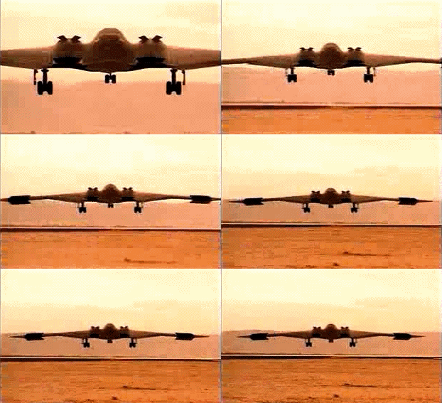
Second sequence: B2 viewed from behind.
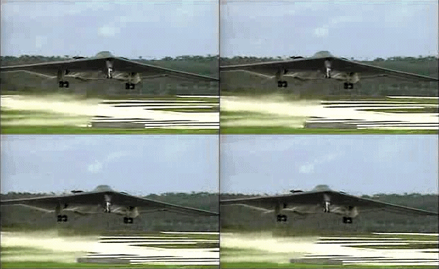
Third sequence: B2 taking off.
Finally, an isolated image by de Panafieu showing these blurry regions:
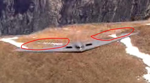
Blurriness near the B2’s trailing edges (by de Panafieu).
Admittedly, this is speculative. Let’s revisit images from the “B2-Spirit in Action” brochure:
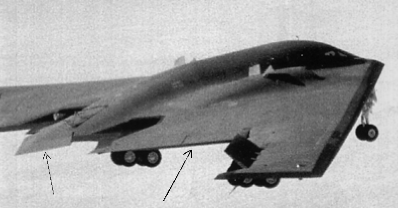
Trailing edge of the B2.
In the foreground, one of the spoilers is fully deployed; this is the B2’s yaw-control mechanism, increasing drag at wingtips. When both are open, they function as air brakes. Near the engines, what appear to be auxiliary air intakes help feed fuel when the aircraft pitches upward. But look at the trailing edge: leftward, near the “beaver tail” used for pitch control—the horizontal stabilizer. What does that black line marked by the right-pointing arrow signify? What purpose do those flaps visible in the plan view serve? Could they constitute a “variable-section flat nozzle”? Logically, such exhaust shouldn’t exist near the “beaver tail,” since that would complicate its articulation.
Similar questions arise when viewing another B2 image dropping massive bombs meant to destroy bunkers. What do those arrows indicate?
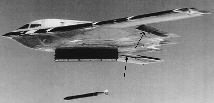
Trailing edge of the B2.
This same photo also shows the wing leading edge; why is it so dark? One contact of mine claims it houses a highly sophisticated radar antenna designed to maintain stealth while locating targets. Possibly.
To be continued...
Previous page Contents of this file
Between February 17 and February 6, 2003: 8,623 views. New visits to this page since February 6, 2003: